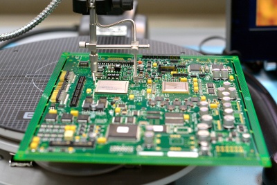
 Printed circuit boards (PCBs) are the "brains" of electronic devices. A PCB contains conductive tracks and pads that electronically connect different components together. This enables them to collectively do their “work”.
Therefore, they need to be manufactured to the highest quality. Regardless of its overall complexity, if a product contains PCBs with "issues" problems will occur.
So what factors do you need to take into consideration during PCB assembly - and how can you avoid common mistakes?1. Supply chain
In order to consistently create high-quality PCBs, month in, month out, you need a robust supply chain. Where are your components coming from? How much do they cost? Can you get them when you need them?
It’s important to strike the right balance between specification, unit cost and ongoing availability. For example, it’s no good buying the right component from a supplier at a low price, only to find a few months down the line that they can no longer provide what you need. Similarly, engineering teams often obtain sample components direct from the manufacturer during the design and prototype stage, but, in the long-run, standard lead-time for the parts and minimum order quantities associated with production volumes can ramp up.
If you are unable to consistently source the components you need, not only will you be unable to assemble your PCBs, but there will be a knock-on impact on the manufacturing cycle of the product into which they are being placed.
Delays such as this can damage an OEM’s reputation and result in monetary losses - and they may even lose customers entirely as a result.
It’s also crucial to verify the source of your components. If they have been procured through franchised distribution, then a well-defined standard goods inwards process should be sufficient protection. However, in some instances it may be necessary to use the grey market - for example, in the case of component obsolescence or during periods of allocation.
If you do go down this route, you should subject your components to stringent anti-counterfeit tests and analysis. The last thing you want is to sell a product containing dodgy parts that go on to fail - with potentially disastrous consequences.
Counterfeit electronic components can vary from parts with missing internal dies right through to older revision components, which have then been re-badged as the latest revision. The first kind typically fail early on in the process. But those parts that have been re-badged can, in theory, pass a number of additional component verification tests without showing signs of their true origin - until it’s too late.
2. Design for manufacture
The design of your PCB might look good on paper or a computer screen - but it can be an entirely different story when it comes to manufacturing it.
For example, there may not be sufficient tolerances between tracks on the board, which later on in the process could result in the circuit shorting out. Or perhaps the design includes a number of components positioned closely together, each with a different thermal mass. Achieving a quality solder joint on each of these components without heat damaging the rest of the circuit board requires expert process engineering skills.
If you are manufacturing a double-sided PCB, there are other factors to consider. Adopting this approach can allow you to fit more components into a limited space or to keep down costs. However, you will need to ensure that, where possible, your largest components are all placed on one side of the board and that this side is passed through the oven second. Otherwise, you risk these components falling off the board. You can use glue to hold down particularly difficult parts, but this requires additional manual work.
3. Design for test
Testing shouldn’t be something you do after you’ve manufactured your PCB - it should be inherent in the entire process.
Unless test points are designed in during conception, it may not be possible to carry out the levels of test you require at a later stage. Clearly, there are differing levels of board complexity and your target market and price point may well determine how far you go in this area. But testing will give you confidence that your "brain" is functioning correctly.
The most popular types of test used in electronic PCB assembly are boundary scan, in-circuit test (ICT) and flying probe. The complexity of your product, the batch volumes, and your budget will all be factors when considering which option best suits your needs - and there are pros and cons of each. In addition to board level tests, you may need to consider if additional "power up" or "functional" tests are built into your manufacturing process.
PCBs are critical to the success of your electronics devices - but PCB assembly presents a number of challenges that have the potential to trip you up along the way. However, if you take steps to secure your supply chain and design your PCB in a way that is conducive to both successful manufacturing and testing, you should be able to overcome these obstacles.

