In-Circuit Test (ICT) and Flying Probe are two of the most popular types of Automated Test Equipment (ATE) used in electronic PCBA assembly.
But what sets them apart? And how can you decide on the test strategy that is going to work best for your assemblies?
In this blog post, we highlight the benefits (and the shortcomings) of both ICT and Flying Probe with a specific focus on three areas: product design, coverage and cost.
1. Product Design
A good quality test programme (also known as good ‘coverage’) will rely on the quality of your Computer Aided Design (CAD) data and schematics.
The CAD data is used to generate the basic test programme, which ensures that information is sourced from the original design rather than any manual interpretation of other data.
Good quality populated, and unpopulated, sample PCBAs are also vital for fine-tuning the test programmes, ‘debugging’ and making any fixtures, so the assemblies physically fit as they were intended.
So thinking about product design for a moment, what are the differences between each test solution which you may want to keep in mind?
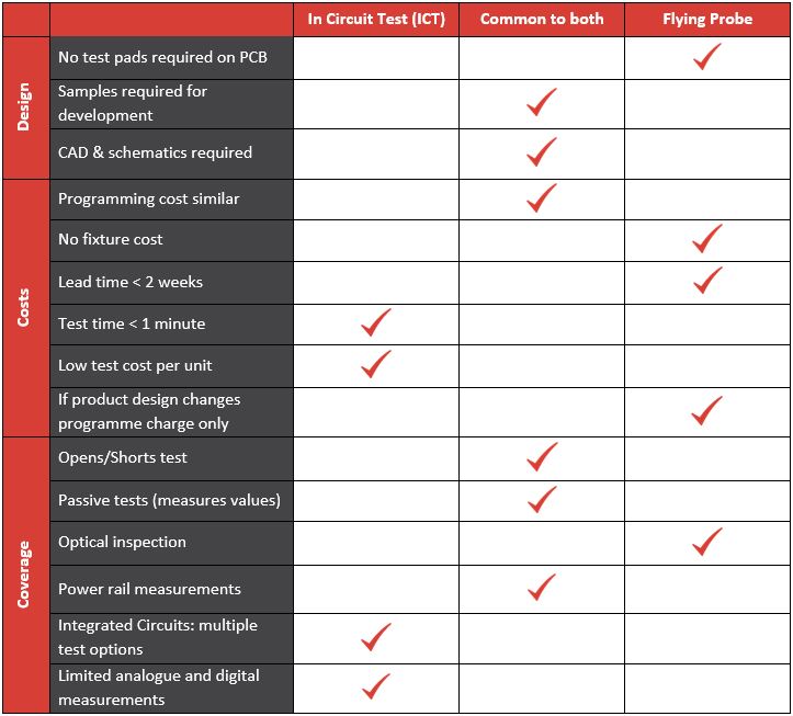
- Flying Probe machines, like those offered by Takaya, can probe the ends of component pads and uncovered vias to get access to the electrical networks.
- ICT will require at least a 50thou wide test pad per net, which has been designed into the PCB up front and which is used as a target for the fixed test probe. Double-sided fixtures can be costly, so these should, ideally, be on one side only of the PCB.
2. Coverage
When we talk about 'coverage’ we're referring to how much of the circuit you are actually able to test.
Both ICT and Flying Probe carry out what is called a ‘manufacturing defects analysis’ or MDA, which allows for the majority of the most common process faults that are likely to occur.
These can include: open circuits (due to insufficient or faulty soldering), short circuits, passive component measurements (resistors and capacitors), diode and transistor orientation, and basic supply voltage measurements.
But, given that these elements are common to both types of testing platform, what sets them apart?
- Most Flying Probe systems will offer some form of limited optical inspection which adds coverage for those components that can’t be accessed electrically. ICT fixtures usually won’t offer the option of optical inspection.
- In addition to vectorless test, integrated circuits (ICs) can also include some powered (albeit basic) functional testing to check the soldering of pins to the PCB through a non-contact capacitive probe or plate. In most cases, flying probe is limited to only vectorless test.
- ICT can also provide limited analogue and digital measurements which flying probe isn't capable of due to the limited number of probes.
3. Cost
The programming cost will depend on the complexity of the assembly, but is broadly the same for either test solution, potentially around £2000 or so. When it comes to other charges associated with test, however, there are some key differences to bear in mind:
- The fixture costs of Flying Probe are usually zero (an ICT fixture in contrast, can run to in excess of £4000.)
- The development lead time for Flying Probe is typically less than a week (ICT can take up to 6 weeks for fixture manufacture and programming.)
- In the event that your product design changes in any way, it will only require a programme change. (In the case of ICT, it could well require a new fixture as well, if any components or test pads have moved.)
- The actual machine test time of ICT is usually less than a minute, which means it is ideal for working quickly through larger batches. (Flying probe on the other hand, can take several minutes, which means it's often more suited to smaller batches.)
- The speed of ICT also means that it is relatively inexpensive, often coming in at less than £1 per unit.(Flying probe is a much slower process, so can cost £50, or more, per assembly.)
If you're still unsure about which test option is best for your product, you may find this simple visual checklist useful in comparing the pros and cons:

When it comes to test, each product will have its own unique requirements.
But by keeping in mind the primary benefits (and the points of difference) of the two platforms, you should feel much better placed to select the best test strategy for your PCBA assembly.

